Thin Substrate Patch Antenna

Patch Antenna on Dielectric Substrate. Open Live Script. This example calculates the performance of the two. Create a Patch Antenna on Low-Epsilon Thin Substrate. This example showcases the analysis of an inset-feed patch antenna on a low-epsilon, low-loss, thin dielectric substrate.
This example showcases the analysis of an inset-feed patch antenna on a low-epsilon, low-loss, thin dielectric substrate. The results are compared with the reflection coefficient and surface currents around the 2.4 GHz, Wi-Fi band for a reference design [1]. The Antenna Toolbox™ library of antenna elements includes a patch antenna model that is driven with a coaxial probe. Another way to excite the patch is by using an inset-feed. The inset-feed is a simple way to excite the patch and allows for planar feeding techniques such as a microstrip line.
The Inset-Feed Patch Antenna The inset-feed patch antenna typically comprises of a notch that is cut from the non-radiating edge of the patch to allow for the planar feeding mechanism. Typical feeding mechanism involves a microstrip line coplanar with the patch.

The notch size, i. Pc Optimizer Pro Crack Keygen Torrent here. e. The length and the width are calculated to achieve an impedance match at the operating frequency. A common analytical expression that is used to determine the inset feed position, the distance from the edge of the patch along its length, is shown below [2]. The patch length and width are L, W respectively. Analysis of the Patch Antenna The overall dimensions of this patch antenna are large and therefore will result in a relatively large mesh (dielectric + metal). The structure is analyzed by meshing it with a maximum edge length of 4 mm and solved for the scattering parameters. The maximum edge length was chosen to be slightly lesser than the default maximum edge length computed at the highest frequency in the analysis range of 2.45 GHz, which is about 4.7 mm.
The analyzed antennas are loaded from a MAT file to the workspace. Discussion The results for this patch antenna are in good agreement with the reference results reported in [1], pg.111 - 114. Reference [1] Jagath Kumara Halpe Gamage,'Efficient Space Domain Method of Moments for Large Arbitrary Scatterers in Planar Stratified Media', Dept. Of Electronics and Telecommunications, Norwegian University of Science and Technology. [2] Lorena I.
Long, 'The dependence of the input impedance on feed position of probe and microstrip line-fed patch antennas,' IEEE Transactions on in Antennas and Propagation, vol. 1, pp.45-47, Jan 2001. Katehi and N. Alexopoulos, 'Frequency-dependent characteristics of microstrip discontinuities in millimeter wave integrated circuits,' IEEE Transactions on Microwave Theory and Techniques, vol. 1029-1035, 1985.
The Effect of Changing Substrate Material and Thickness on the Performance of Inset Feed Microstrip Patch Antenna Liton Chandra Paul 1, Md. Sarwar Hosain 2, Sohag Sarker 2, Makhluk Hossain Prio 3, Monir Morshed 4, Ajay Krishno Sarkar 3 1, Pabna University of Science & Technology,, Bangladesh 2, Pabna University of Science & Technology, Pabna, Bangladesh 3 Department of Electrical and Electronic Engineering, Rajshahi University of Engineering & Technology, Rajshahi, Bangladesh 4 Department of Information and Communication Technology, Mawlana Bhashani Science and Technology University,Tangail, Bangladesh Email address. Abstract: In order to design a microstrip patch antenna at first the designer is to select the substrate material and it’s thickness. So, if the designer has a clear conception about the effect of changing substrate material and it’s thickness on the performance of the antenna, it will be easier to design an antenna.
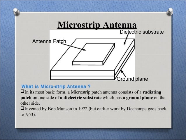
Appropriate selection of dielectric material and it’s thickness is an important task for designing a microstrip patch antenna. This paper represents that how antenna performance changes when we vary substrate material and it’s thickness. The designed inset feed rectangular microstrip patch antenna operates at 2.4GHz (ISM band). Keywords: Inset Feed, Dielectric Constant, Substrate Thickness, Bandwidth, Return Loss, Gain, Directivity, Radiation Efficiency. Introduction Microstrip patch antennas consist of a metallic patch on a grounded substrate.The microstrip patch antenna first took form in the early 1970’s and interest was renewed in the first microstrip antenna proposed by Deschamps in 1953[].
Microstrip antennas have found widespread applications for microwave as well as millimeter wave systems [].Compatible devices are widely used in our daily lives such as mobile phones, laptops with wireless connection, wireless universal serial bus (USB) dongles etc and microstrip patch antenna plays a very significant role for the miniaturization of these devices []. The applications in present-day mobile communication systems usually require smaller antenna size in order to meet the miniaturization requirements of mobile units. Thus, size reduction and bandwidth enhancement are becoming major design considerations for practical applications of microstrip antennas. The microstrip patch antennas are well known for their performance and their robust design, fabrication and their extent usage. The inherently narrow impedance bandwidth is the major weakness of a microstrip antenna []. Although we used rectangular shaped patch but the radiating patch can be of any geometrical configuration like square, rectangle, circular, elliptical, triangular, E-shaped, H-shaped, L-shaped, U shaped etc. The material which has the dielectric constant in the range of 2.2 ≤ ε r ≤ 12 can be used as substrate [].